Difference between revisions of "Rockchip-isp1"
| Line 31: | Line 31: | ||
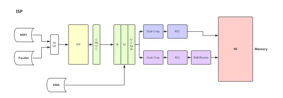
The completed block diagram can not be pasted from datasheet to here, below diagram is a abstract version: | The completed block diagram can not be pasted from datasheet to here, below diagram is a abstract version: | ||
| − | [[File:Blocks.png|1200px]] | + | [[File:Blocks.png|1200px|Blocks.png]] |
== MIPI Details == | == MIPI Details == | ||
| Line 53: | Line 53: | ||
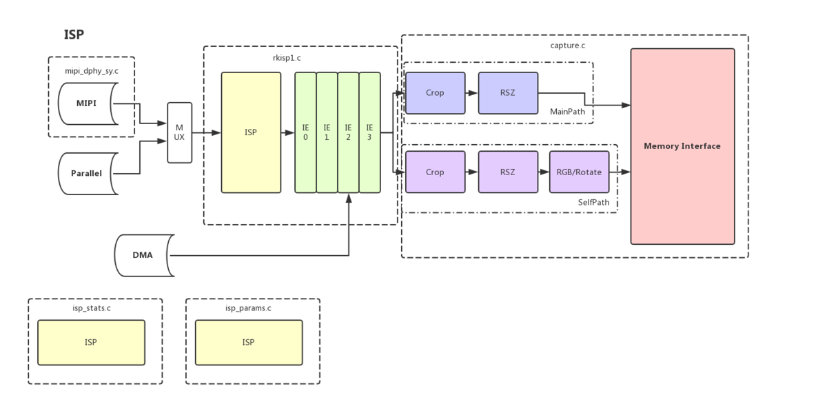
=== Block diagram === | === Block diagram === | ||
| − | + | [[File:Code.png|1200px]] | |
=== Sensor Driver Requirement === | === Sensor Driver Requirement === | ||
Revision as of 12:36, 30 November 2017
NOTE: Under Construction
Contents
Overview
The document below provide basical informations about the rockchip-isp1 driver driver and Image Signal Processing block on Rockchip SoC with examples and details.
Hardware
More detailed information could be found in TRM chapter "Image Signal Processing", "MIPI D-PHY" , but they are only available under NDA.
ISP Details
ISP comprises with:
- MIPI serial camera interface
- Image Signal Processing
- Color Processing
- Image Effects
- Superimpose
- Luminance / Chrominance Splitter
- Crop
- Main Resize
- MPMUX for selection of main patch data flow
- Control unit
Block diagram
The completed block diagram can not be pasted from datasheet to here, below diagram is a abstract version:
MIPI Details
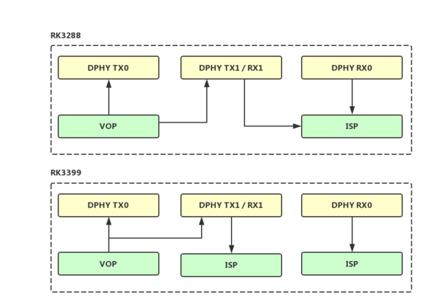
There are three D-PHY instances in rk3288/rk3399, their connection are shown as following figure:
Software
Driver
rockchip-isp1 is a V4L2 based driver for Image Signal Processing block on Rockchip SoC. Compared to the earlier driver rk-isp10, it use Media Controller framework, which it's different from plain v4L2. While the plain v4L2 had a view of the device as a plain DMA based image drabber which connects the input data to the host memory, the Media Controller takes into consideration the fact that a typical video device might consist of multiple sub-devices.
Media Controller Basics
Please read below link carefully, especially if you don't have use it before.
Block diagram
Sensor Driver Requirement
The sensor driver should implement controls in the following table.
| Controls | Description | R/W | Needed by |
|---|---|---|---|
| V4L2_CID_VBLANK | Vertical blanking. The idle period after every frame during which no image data is produced. The unit of vertical blanking is a line. Every line has length of the image width plus horizontal blanking at the pixel rate defined by V4L2_CID_PIXEL_RATE control in the same sub-device.
|
R | Ae |
| V4L2_CID_HBLANK | Horizontal blanking. The idle period after every line of image data during which no image data is produced. The unit of horizontal blanking is pixels. | R | Ae |
| V4L2_CID_EXPOSURE | Determines the exposure time of the camera sensor. The exposure time is limited by the frame interval. Drivers should interpret the values as 100 µs units, where the value 1 stands for 1/10000th of a second, 10000 for 1 second and 100000 for 10 seconds. | R/W | Ae |
| V4L2_CID_ANALOGUE_GAIN | Analogue gain is gain affecting all colour components in the pixel matrix. The gain operation is performed in the analogue domain before A/D conversion. | R/W | Ae |
| V4L2_CID_DIGITAL_GAIN | Digital gain is the value by which all colour components are multiplied by. Typically the digital gain applied is the control value divided by e.g. 0x100, meaning that to get no digital gain the control value needs to be 0x100. The no-gain configuration is also typically the default. | R/W | Ae |
| V4L2_CID_PIXEL_RATEP | Pixel rate in the source pads of the subdev. This control is read-only and its unit is pixels / second. | R | Ae |
| V4L2_CID_LINK_FREQ | Data bus frequency. Together with the media bus pixel code, bus type (clock cycles per sample), the data bus frequency defines the pixel rate (V4L2_CID_PIXEL_RATE) in the pixel array (or possibly elsewhere, if the device is not an image sensor). The frame rate can be calculated from the pixel clock, image width and height and horizontal and vertical blanking. While the pixel rate control may be defined elsewhere than in the subdev containing the pixel array, the frame rate cannot be obtained from that information. This is because only on the pixel array it can be assumed that the vertical and horizontal blanking information is exact: no other blanking is allowed in the pixel array. The selection of frame rate is performed by selecting the desired horizontal and vertical blanking. The unit of this control is Hz.
|
R | mipi-dphy |
Linux
User applications
The applcation for plain v4L2 capture device still can be used(like gstreamer v4l2src plugins, v4l2ctl), but the media controller must be setup in a proper state before starting capture.
The applications for Video Capture with rockchip-isp1 driver should do things like the following commands:
media-ctl -l '"rockchip-sy-mipi-dphy":1->"rkisp1-isp-subdev":0[1]'
media-ctl -l '"rkisp1-input-params":0->"rkisp1-isp-subdev":1[1]'
media-ctl -l '"rkisp1-isp-subdev":2->"rkisp1_selfpath":0[1]'
media-ctl -l '"rkisp1-isp-subdev":2->"rkisp1_mainpath":0[1]'
media-ctl -l '"rkisp1-isp-subdev":3->"rkisp1-statistics":0[1]'
# Media graph have been initializated when kernel driver probing, so above commands don't have to be called, though please note that they can be changed in the runtime
# Set pad formats
## rkisp1 source pad
media-ctl -set-v4l2 '"rkisp1-isp-subdev":2[fmt:YUYV2X8/800x600]'
## rkisp1 sink pad == sensor source [ad]
media-ctl --set-v4l2 '"rkisp1-isp-subdev":0[fmt:SRGGB10/800*600]'
media-ctl --set-v4l2 '"ov2685 7-0010":0[fmt:SRGGB10/800*600]'
# Set link(Assume there are two sensors in one mipi-phy)
## Enable sensor1
media-ctl -l '"ov2685 7-0010":0->"rockchip-sy-mipi-dphy":0[1]'
## Disable sensor2
media-ctl -l '"ov5695 7-0036":0->"rockchip-sy-mipi-dphy":0[0]'
# Start capture
v4l2-ctl xxxxxxx
Integrate 3A algorithm
Multi sensors
Multi paths
Record, Preview, Still Capture in different resolution at a time
Gstreamer
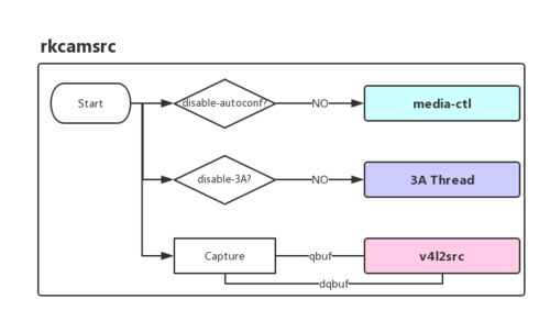
We have write a gstreamer plugin, rkcamsrc, which is simply modified from gstreamer v4l2src plugin.
Please refer to readme in github for usage.
Android
Camera Hal3
https://source.android.com/devices/camera/camera3
Reproduce
The driver currently can run on ASUS Tinker Board and Firefly-RK3288-Reload + Rockchip Debian/Yocto SDK.
Source Code
Kernel
- 4.15 + FORMLIST Patches
- Rockchip 4.4 BSP
Sensor Driver
Device Tree
Test Command
cat /sys/class/video4linux/video*/name
# get self_path videox and main_path videox+1
gst-launch-1.0 rkcamsrc device=/dev/videox+1 io-mode=4 disable-3A=true ! videoconvert ! video/x-raw,format=NV12,width=640,height=480 ! kmssink
Others
Topology
Media device information
------------------------
driver          rkisp1
model           rkisp1
serial
bus info
hw revision     0x0
driver version  0.0.0

Device topology
- entity 1: rkisp1-isp-subdev (4 pads, 5 links)
            type V4L2 subdev subtype Unknown flags 0
            device node name /dev/v4l-subdev0
        pad0: Sink
                [fmt:SBGGR10_1X10/800x600 field:none
                 crop.bounds:(0,0)/800x600
                 crop:(0,0)/800x600]
                <- "rockchip-sy-mipi-dphy":1 [ENABLED]
        pad1: Sink
                <- "rkisp1-input-params":0 [ENABLED]
        pad2: Source
                [fmt:SBGGR10_1X10/800x600 field:none
                 crop.bounds:(0,0)/800x600
                 crop:(0,0)/800x600]
                -> "rkisp1_selfpath":0 [ENABLED]
                -> "rkisp1_mainpath":0 [ENABLED]
        pad3: Source
                -> "rkisp1-statistics":0 [ENABLED]

- entity 2: rkisp1_selfpath (1 pad, 1 link)
            type Node subtype V4L flags 0
            device node name /dev/video0
        pad0: Sink
                <- "rkisp1-isp-subdev":2 [ENABLED]

- entity 3: rkisp1_mainpath (1 pad, 1 link)
            type Node subtype V4L flags 0
            device node name /dev/video1
        pad0: Sink
                <- "rkisp1-isp-subdev":2 [ENABLED]

- entity 4: rkisp1-statistics (1 pad, 1 link)
            type Node subtype V4L flags 0
            device node name /dev/video2
        pad0: Sink
                <- "rkisp1-isp-subdev":3 [ENABLED]

- entity 5: rkisp1-input-params (1 pad, 1 link)
            type Node subtype V4L flags 0
            device node name /dev/video3
        pad0: Source
                -> "rkisp1-isp-subdev":1 [ENABLED]

- entity 6: rockchip-sy-mipi-dphy (2 pads, 2 links)
            type V4L2 subdev subtype Unknown flags 0
            device node name /dev/v4l-subdev1
        pad0: Sink
                [fmt:SRGGB10_1X10/3280x2464 field:none]
                <- "imx219 2-0010":0 [ENABLED]
        pad1: Source
                [fmt:SRGGB10_1X10/3280x2464 field:none]
                -> "rkisp1-isp-subdev":0 [ENABLED]

- entity 7: imx219 2-0010 (1 pad, 1 link)
            type V4L2 subdev subtype Sensor flags 0
            device node name /dev/v4l-subdev2
        pad0: Source
                [fmt:SRGGB10_1X10/3280x2464 field:none]
                -> "rockchip-sy-mipi-dphy":0 [ENABLED]


